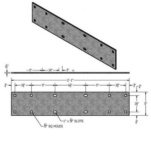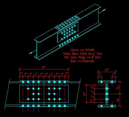

Suggested detailing showing possible solutions for shear wall top plate discontinuities are shown below. bar diagrams, bar arrangement, splices and laps, mechanical connections. The wall sheathing cannot be used to splice the wall top plates at these locations, in accordance with the American Wood Council’s Special Design Provisions for Wind and Seismic (SDPWS) Section 4.1.4. Identification of products and materials included by sheet and detail number. The force at a splice location can be calculated by determining the net shear acting along the shear wall (shear wall shear minus the diaphragm shear), then constructing a force diagram as shown in Figures 1 and 3 below. Any splice connection must be capable of transferring calculated tension and compression forces. This isn’t typically an issue unless a disruption or discontinuity in the top plates must occur.

Standard & project-specific profiles & sizes. When designing shear walls, it’s important to consider forces that are applied along the top plates, and to recognize that the top plates can be under tension and compression at the same time. HHS-12-15-2183 DESIGN OF SPLICE PLATES FOR BOTTOM CROSS BEAM ISMB 600 Properties of ISMB 600 as per IS 808:1989 Size of top flange 20.3 mm 210 mm Size of web 12 mm 559.4 mm Size of Bottom flange 20. EZ Edge Fascia and Coping Features and Benefits: Factory fabricated and field proven. When ange splice plates are used, single plate shear connections should be used to carry the shear force be-tween the beam and column and to facilitate eld erection. This can be accomplished with eld shims between the splice plates and beam anges. In order to address this, splice connections should be designed and detailed so they’re capable of transferring loads around the discontinuity. in the details for ange splice plates and beams through the column. It will act as a beam with a uniform load and be pinned on each end. In some cases, a shear wall’s top plates are used as chords and/or collectors for a diaphragm, meaning that discontinuities in the top plates create discontinuities in lateral load paths. I have a client who has a 9 long channel and needs it to be 12. Disruption of shear wall top plates can occur for many reasons-e.g., the presence of a continuous structural steel column within the wall, installation of plumbing vents, change in wall widths, or a slight jog in wall position.


 0 kommentar(er)
